1. Usage Reference

As ACCS is completely integrated within ANSYS Workbench, one simply needs to run Workbench to have access to it. For step-by-step tutorials, please refer to the Workshops section.

1.1. ACCS RTM Solver Workflow

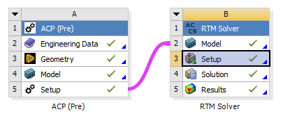
A typical Workbench ACCS RTM Solver workflow for composite structures looks as follows:

1.1.1. Typical Workflow With ACP

_images/RTM_workflow1.png

Fig. 1.1.2 Typical ACCS RTM Solver workflow for composites in Workbench.

The material properties are defined in the Engineering Data module. A shell model is generated in DesignModeler or in SpaceClaim or in any other CAD tool, then it is worked out in ACP (Pre) module to build a solid finite element model of the composite structure that will be transferred to the “RTM Solver” module where the flow will be calculated.

1.1.2. Workflow With Only ACCS RTM Solver

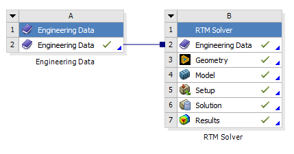
_images/RTM_workflow2.png

Fig. 1.1.3 ACCS RTM Solver workflow with only the solver.

For workflows with only an ACCS RTM Solver, an external engineering data module is required to be created, and then imported into the model.

1.1.3. Workflow With External Model and ACP

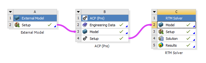
_images/RTM_workflow3.PNG

Fig. 1.1.4 ACCS RTM Solver workflow with External Model and ACP.

1.2. ACCS RTM Solver Material Definitions

There are two types of materials needing to be defined in ACCS RTM Solver. These are fabrics and resins. This section will detail the compulsory properties for each of these material types, as well as optional ones.

1.2.1. Fabric Material Definition

_images/materials_fabric.PNG

Fig. 1.2.9 An example definition of a fabric material in ACCS RTM Solver.

For fabrics, only permeability is required to be defined.

1.2.2. Resin Material Definition

_images/materials_resin.PNG

Fig. 1.2.10 An example definition of a resin material in ACCS RTM Solver.

For resins, only viscosity is required to be defined. However, if gravitational effects are to be simulated, density will need to be set.

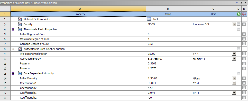
_images/materials_resin_gelation.PNG

Fig. 1.2.11 An example definition of a resin material in ACCS RTM Solver with gelation properties and density set.

If the gelation properties of a material are set, a cure kinetic equation and cure defined viscosity are required to be defined. The ACCS RTM Solver currently supports Nth Order, Autocatalytic and Kamal-Sourour cure kinetic equations.

Note

For workflows containing only ACCS RTM Solver, engineering data will need to be defined in an external engineering data module, then imported into the solver.

1.3. ACCS RTM Solver Post-Processing Options

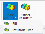
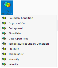
Several results can be added to the model, allowing for simulation specific post-processing options like Fill, Infusion Time, and Flow Rate. These options can be found by selecting the “Main Results” and the “Other Results” buttons, as shown in the following image:

_images/RTM_Results_available.png

Fig. 1.3.7 Results available during ACCS RTM Solver analysis.

1.3.1. Fill

This result shows the fill of each node, as the simulation progresses.

1.3.2. Infusion Time

This result shows for each node, the time it was fully filled.

1.3.3. Degree of Cure

This result shows the degree of cure for each node.

Warning

Degree Of Cure Results: This result only displays values when gelation is set for a material.

1.3.4. Boundary Conditions

This result shows whether a time dependent boundary condition is set for a node.

1.3.5. Entrapment

This result shows the entrapment pressure in the model for each node, if entrapement is set.

1.3.6. Flow Rate

This result shows the flow rate for each node.

1.3.7. Gate Open Time

This result shows the open time of the inlet that filled each node.

1.3.8. Pressure

This result shows the pressure values at each node.

1.3.9. Temperature Boundary Conditions

This result shows whether a temperature boundary condition is set for a node.

1.3.10. Velocity

This result shows the velocity values at each node.

1.3.11. Viscosity

This result shows the viscosity values at each node.

1.3.12. TG

This result shows the TG values at each node.

1.3.13. Resin State

This result shows the Resin State of each node: 1 = Liquid, 2 = Rubbery, 3 = Glassy.

1.3.14. Thermal Expansion

This result shows the Thermal Expansion at each node.

1.3.15. Cure Shrinkage

This result shows the Cure Shrinkage at each node.

1.3.16. Total Volume Change

This result shows the Total Volume Change at each node.

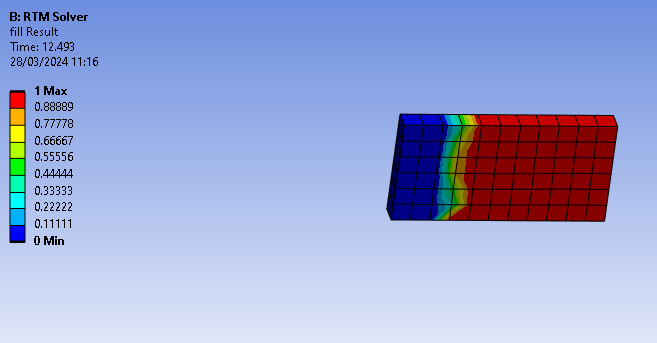
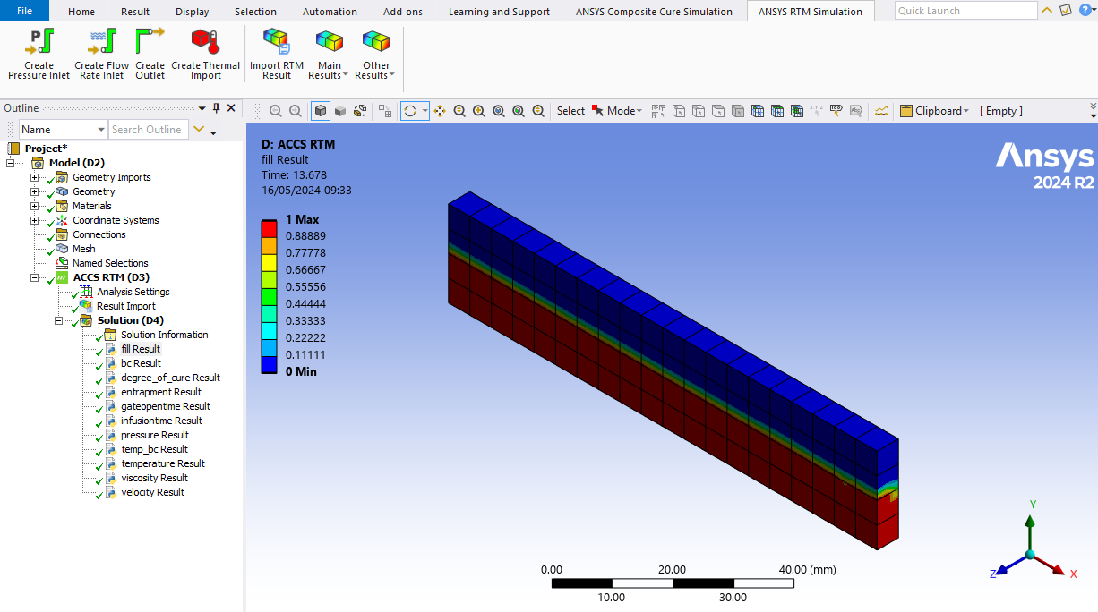
Once the model is solved, the results can be reviewed by clicking on them. Here in the example we can see the fill at 12.5 seconds in the model.

_images/RTM_solution_plots.PNG

Fig. 1.3.8 Solution plots example. Fill of each node at 25 seconds

_images/RTM_Mechanical_results.png

Fig. 1.3.9 Extra results available in the “Other Results” tab.

Warning

Results Warning: It is important to note that the above results will only work with the ACCS RTM Solver.

1.4. ACCS RTM Solver Importing Results

  1. Ensure that the mesh in mechanical is identicial to that of the result.

  2. Select “Import Result” in the ACCS RTM Solver ribbon to add a import result load. Click on the load, and select the H5 file you wish to import from.

  3. Set the analysis setting “Result Only” to True.

  4. Choose the results you want to view from the ACCS RTM Solver ribbon.

  5. Press solve.

_images/RTM_Result_Import.PNG

Fig. 1.4.7 Example of an imported result.

1.5. Using command line to run ACCS RTM Solver

  1. Setup your model in Ansys as normal.

  2. In Ansys Mechanical select “Write Input File” in the Solution ribbon to write the input files (the solution tree object needs to be selected to see this tab).

  3. Run the RTM Solver by command line with > %ProgramFiles%\LMAT\ACCS\v3.1_WB25.1\RTM\Resin_Infusion.exe <RTWFilePath> where <RTWFilePath> is the filepath of the RTW file for the model.

  4. Import the H5 result back into Ansys to view the result.

_images/write_input_file.png

Fig. 1.5.5 Write Input File button.

1.6. Known Limitations

  1. The graph from the results will only show the first second. However the animation and tabular data will display as normal.

  2. ACCS properties will not be shown in the Engineering Data section of the ACCS RTM Solver module. Please use an external Engineering Data and import it in, or define the material property in ACP if you are defining layups.
  3. ACCS RTM Solver only supports ACP defined layups.